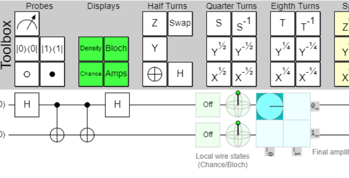

The equation for a graph state suggests an all-to-all recipe: apply one CZ gate for every edge. Real processors do not offer arbitrary connectivity. The benchmark therefore prepares a complicated graph-state representative using only a one-dimensional nearest-neighbour chain.
Brickwork on a line
Place the data qubits in the order 0, 1, …, n−1. A single CZ layer can act on every other edge in parallel. The next layer shifts by one site:
even layer: (0,1) (2,3) (4,5) ...
odd layer:       (1,2) (3,4) (5,6) ...
Alternating these layers produces the familiar brickwork pattern. No two gates in one layer share a qubit, so they can be scheduled simultaneously. The supplied benchmark repeats odd and even layers until the CZ depth scales with the number of qubits.
Why local Clifford gates change the graph
After each entangling layer, the construction applies a random local choice equivalent to √X or S√X on each qubit. H, S, √X and CZ are Clifford gates: they map Pauli operators to Pauli operators under conjugation. The state therefore remains a stabilizer state throughout this prefix.
The local gates are not decorative. Interleaving them with nearest-neighbour CZ gates continually changes which stabilizers are local and which are extended. In the graph-state picture, local Clifford transformations correspond to graph transformations such as local complementation. A physically local circuit can therefore represent a graph with much richer effective connectivity than the hardware chain itself.
The non-Clifford measurement basis
A pure Clifford circuit is efficiently simulable with a stabilizer tableau. The benchmark avoids ending there. After the graph-state prefix, every data qubit receives the same face-state basis rotation:
theta = math.acos(1 / math.sqrt(3))

for q in range(n):
    circuit.tdg(q)
    circuit.h(q)
    circuit.rz(theta, q)
    circuit.h(q)
The angle points the measurement axis toward a face of the Bloch-sphere stabilizer octahedron. This adds non-Clifford magic before computational-basis measurement. The experiment is hard by design in two different directions: the Clifford prefix creates entanglement that burdens tensor networks, while the final basis burdens stabilizer decompositions.
A compact pedagogical constructor
import random
from qiskit import QuantumCircuit

def brickwork_graph_prefix(n, depth, seed=1729):
    rng = random.Random(seed)
    qc = QuantumCircuit(n)
    qc.h(range(n))

    for layer in range(depth):
        offset = layer % 2
        for q in range(offset, n - 1, 2):
            qc.cz(q, q + 1)

        for q in range(n):
            if rng.getrandbits(1):
                qc.s(q)
            qc.sx(q)

    return qc
This code expresses the ansatz, not the exact frozen benchmark instance. For reproduction, the QASM files and their hashes are authoritative. The tutorial constructor is valuable because it exposes the architecture and lets readers experiment with smaller values of n and depth.
Two circuits, two purposes
The repository contains a bare circuit for sampling and a checked circuit with ancillas for spacetime error detection. The checked version does not define a different mathematical target; it embeds additional observables that reveal some errors during execution. Part 5 develops that verification layer.
Part 3 turns the constructor into a complete Qiskit workflow with measurement, simulation and the repository’s safe inspection commands.