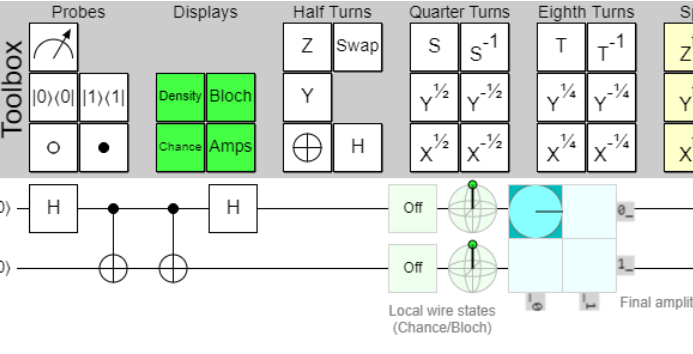

The minimal-circuit proposal organizes the Fibonacci experiment as a ladder. Three qubits expose fusion amplitudes, five qubits add the topological twist, and nine qubits support a braid. Each rung introduces a new physical statement and a new opportunity for a wiring or convention error.
Passing the ladder means that ideal ordinary-qubit circuits reproduce the target Fibonacci mathematics. These small circuits remain classically tractable and are not evidence of quantum advantage.
Three qubits: fusion amplitudes
The first circuit prepares the two allowed fusion channels with golden-ratio weights. Its full state fidelity is \(1.0\), while the forbidden branching weight is below \(6\times10^{-31}\). This is a compact test of the fusion rule and of the basis convention used to turn a fusion tree into computational-basis bits.
The important point is that the test compares complete complex statevectors, not only a final histogram. A probability-only match could conceal a wrong relative phase that later breaks interference.
Five qubits: the twist phase
The second rung embeds a \(\tau\) twist in a five-qubit register. The final state fidelity is \(0.9999999999999949\), and the inferred phase error is below \(5\times10^{-15}\) radians. This rung checks that the complex phase conventions are consistent across preparation, local operations, and readout.
Fusion and twist are already nonclassical structures, but the defining non-Abelian test requires the nine-qubit braid.
Nine qubits: reconstructing the full source circuit
The source diagram contains controlled F-moves, CNOT and Toffoli relabelling steps, tadpole operations, an exchange, and a final complex filter. The corrected reconstruction executes every source-level block on a fixed nine-qubit Qiskit register. Its decisive ideal results are:
| Check | Value |
|---|---|
| Full fusion state fidelity to Eq. (34) | \(0.9999999999999671\) |
| Full braid state fidelity to Eq. (37) | \(0.9999999999999536\) |
| Phase-aligned braid residual | \(6.03\times10^{-12}\) |
| Complex-filter pass probability | \(1.0\) |
| Maximum readout-subspace leakage | \(3.56\times10^{-23}\) |
These numbers were not obtained by continuously fitting gates or amplitudes. Three discrete fixed-register ambiguities had to be resolved.
Why a literal diagram transcription failed
First, one fusion-readout F-box appears to use a control that is not adjacent at that lattice position. Replacing it with the geometrically adjacent edge reproduces the target exactly. Second, the braid rearranges logical edge roles even though the hardware wire labels do not move; the final readout therefore needs a fixed-register role map. Third, the transition between Eqs. (36) and (37) requires an open control on one disentangling X operation.
The corrections were identified through lattice adjacency, the paper’s equations, and exhaustive discrete searches. Blind global wire permutations and alternative literal-dot interpretations were also tested and retained as negative evidence. That falsification record is valuable: it shows why the accepted circuit is not simply the first version that happened to look plausible.
The source braid and the order-comparison extension
The paper’s nine-qubit experiment implements a single counterclockwise exchange and validates its complex target with a conjugated filter. The two-order observable used in this project is an additional declared extension: it embeds the logical \(B_1B_2\) versus \(B_2B_1\) comparison in the same readout qubit. It is not presented as a second source-drawn circuit.
The extension gives \(P(q_2=0)=1\) for one order and \(1/\phi^2\) for the other. Their total-variation distance is \(1/\phi\). After the best possible global-phase alignment, the output-state distance remains \(0.8740\), so the measurement contrast is not a phase convention artifact.
Exactness is necessary, not sufficient
At source level the primary circuit has depth 42. That sounds modest, but the count hides 13 four-controlled F gates and nine Toffolis. A hardware compiler must decompose those structured blocks into native one- and two-qubit operations and route them across a sparse coupling graph. The next article shows why this turns an exact nine-qubit success into a hardware-readiness failure.